Introduction
Importance and Necessity of Research
Research Methodology
Validation of Research Instrument: DesignBuilder Software
Application of the Research
Phases of the Research
Climatic Conditions of Cities under Study
Yazd
Tabriz
Shahrud
Bandar Abbas
Employ solar energy in case of heating demand
Area of the Sample Temporary Housing
The examined shapes to obtain the optimal shape of temporary housing
Suitable Angle of the Walls of the Shapes
The Usable Area with Enough Headroom (in Terms of Height) in the Shapes under Study
Shapes with 1 m base wall (Total Height of 4 m)
Shapes without base wall (Total Height of 3 m)
Simulation Stages in DesignBuilder
Analysis of Findings
Investigating the energy required to build a temporary housing in shapes with a 1-meter base wall (total height of 4 m)
Investigating the energy required to build a temporary housing without base wall (total height of 3 m)
Selecting the Shape of Temporary Housing in Four Climates under Study
Conclusion
Introduction
Typically, after a natural disaster with great dimensions and high depth, the residential areas become useless, and therefore, the first issue that creates security and peace among the affected people is to have a good housing for the family gathering [1]. Each year, about 3 million people on average (in the world) become homeless after disasters and about 80% encompasses those who have lost their homes in earthquakes [2]. Engineering statistics and possibilities suggest that a severe earthquake occurs every four years in Iran the result of which is 97% demolition of rural houses in the earthquake-struck area [3]. Therefore, currently many nations consider post-disaster provision plans (from the emergency phase to the permanent housing) before a disaster occurs [4].
One of the phases of relief, is the temporary housing of the survivors in the post-disaster harsh conditions [5]. Tackling the homelessness problem and housing of the disaster-affected people is a major issue that is of special importance in the phase of post-disaster confrontation [6].
For a family, housing should provide safety and comfort, and a sense of belonging [7]. The presented plan (post-disaster housing) should be according to the climate and conditions of the region while observing technical and architectural principles [8]. In cases when there is a risk of damage due to the harsh climatic conditions, providing emergency housing is a human issue and the consequences of permanent and professional housing are not forthcoming [9].
After disaster, provision of housing and supplying the need of the affected people are of special importance.
Of important features to improve temporary housing is to have good lighting and heating and ventilation [10]. high speed of construction for victims in shorter time [11], providing a good quality of life [12], compatible with the environment, climate and weather [13], architectural components and local landscaping [14], providing private space [15]; that should be considered when designing and constructing temporary housing.
Thermal comfort in the housing is a priority when designing and building temporary housing.
Relief seekers need a good housing in terms of safety, culture and climate, with simple maintenance [16]. The problems of current housings are lack of privacy, irritating cold and heat, inappropriate, and, non-standard tents and CONEX boxes [17].
Results of the study by Asefi et al. on assessing the satisfaction of temporary housing after the earthquake in Sarand village indicated that: there is low satisfaction of the physical and socio-cultural components, and, a moderate dissatisfaction of technical components [18].
Much research suggest that considering climatic conditions, protection against heat, cold, wind and rain is among strategies to improve temporary housings [10, 13, 15, 19, 20].
In order to provide thermal comfort in the temporary housing, it is necessary to consider architectural design of the building.
The study began with the following hypothesis: The form of the building influences energy saving, and, changing the shape of the temporary housing from a cube into shapes with sloping and curved walls reduces energy Demand of the temporary housings. The aim of the present study was to obtain the most appropriate shape.
Importance and Necessity of Research
Usually, in post-disaster conditions, there are problems in supplying fossil fuels (oil, electricity, gas, etc.) for the victims. Therefore, it is essential to design temporary housings which are less dependent to fossil fuels. Energy plays a pivotal role in obtaining economic, social and environmental development in line with human development [21]. Considering the importance of addressing post-disaster housing, the base of design should be to pay special attention to the Iranian users’ culture and their lifestyle proportional to the climatic conditions of Iran [22]. Since there is a direct relationship between the building shell and its energy consumption, it is essential to consider the problem of energy saving when designing the building architecture [23]. Passive architecture, compliance of the building with the climate [24, 25] and providing the comfort conditions for the residents using new energies would save fossil fuels consumption. Passive heating and cooling are not new concepts. They have been used in many parts of the world with different techniques and different materials for centuries [26].
Regarding that in the crisis conditions, providing energy through fossil fuels and electricity is challenging and time-consuming, it is important and necessary to design temporary housing that could provide the comfort conditions of its residents.
Delay in temporary housing provision is one of the causes of dissatisfaction among victims which exacerbates traumatic stress (Authors). Unfortunately, temporary housing is costly and delayed [27]. One of the causes of delayed temporary housing is failure in using advanced methods in their construction. Reduced construction time for temporary housing, and timely and rapid utilization are also of significant importance.
In addition to supply thermal comfort of the users this study focused on providing temporary housing with a people-centered approach and accelerating the resettlement of victims. Uniform construction of the outer shell (or interior walls) of the housings using 3D printing technology could accelerate the provision of temporary housing. For example the first 3D-printed residential home, engineered by the tech startup Apis Cor, took less than a day to construct (Figure 1). A mobile 3D printer created the building’s concrete walls and partitions as a fully connected structure, rather than printing the building in panels at an off-site facility as is usually done, the company said.

Figure 1.
The first demonstration of the 3D printing technology is a cozy, 400-square-foot (37 square meters) home with an unusual, curved shape [28].
In industrial construction methods where the ceiling and the walls are made separately and then connected together, it takes much time to build a piece, lifting the piece, and aligning the pieces together, which eventually slows down the construction process. The idea of using 3D printing technology came out when dealing with post-disaster temporary housing to accelerate construction speed relative to other construction methods. To this purpose, it was proposed to simultaneously execute roof and walls in a uniform manner. One of the most important factors affecting the energy consumption of a building is the thermal resistance of its external shell. An air layer is used as thermal insulation to increase the thermal resistance of the walls. When constructing a building using 3D printing technology, it is common to print the inner and outer edges of the wall and an air gap will be remain between these two layer as thermal insulation which will significantly save fossil fuels (Figure 2). It is suggested to use common local construction materials when building post-disaster temporary housing. Concrete is proposed to be used due to its high application in construction and its use in a construction 3D printer. The type of materials used was the confounding variable and it was controlled for in this study; non-coarse-grained concrete materials are selective materials that can also be used with foam concrete.

Research Methodology
This was an applied study with a quantitative approach. The research method used in this study was the causative method and computer simulation. Simulation is among suitable methods in architecture studies, and, it provides the opportunity to construct and investigate numerous construction models [30]. The independent variable was the shape of temporary housing, and the dependent variable was the energy demand of the building to supply thermal comfort to building occupants. In this study, the controlled variables are parameters related to openings, materials, interior equipment and the number of occupants. Causative research method is one of the basic techniques used to collect data (especially in the architecture). The experiment is repeatable in controlled conditions where one or more independent variables are manipulated to test the hypothesis [31]. DesignBuilder was the research instrument in this study. This software employs EnergyPlus base solver to analyze the processes of thermal transfer governing the building [32].
Validation of Research Instrument: DesignBuilder Software
To examine the accuracy of the results of DesignBuilder, an experimental sample of ASHRAE Standard 140 Case 600 (2001) was tested, and, the obtained results were compared to the results in the manual. The software version was validated and approved by ASHRAE Standard [33]. Analyses and calculations were conducted in EnergyPlus based on heat exchange in the entire simulation area [34].
EnergyPlus is a common simulation instrument in energy and construction sector, and, many studies are conducted and published in this sector using EnergyPlus, including the study by Nasrollahi [35], Ansarimanesh [36], Sarkardehi [37], Amir Fard & et al. [38] And Mohammadi [39], etc. According to the results of Zomorrodian et al., DesignBuilder has a good performance in anticipating energy consumption and internal temperature of the spaces [40].
Application of the Research
This study could be applied for architectural design and post-disaster temporary housing. Results of the study could be used to reduce the buildings’ dependence on fossil fuels, and, to use renewable energies.
Phases of the Research
In first a general study was conducted on four different climates in Iran: In the summer, four different climates are found in Iran including: “hot and dry”, “hot and semi-arid”, “hot and humid”, and “moderate summer:”, compared to the winter with a combination of “cold”, “very cold” and “moderate” climate in four cities of Yazd, Bandar Abbas, Shahrud and Tabriz was conducted, and then, the area in need for temporary housing was investigated. Afterwards, simulation of the shapes in the building materials software for temporary housing was considered as Table 1(a). The study was conducted in two general phases. In the first phase, the energy Demand of eleven shapes was simulated and calculated in Yazd. After comparing the energy demand of the mentioned shapes, the selected samples of the second phase (from the results of the first phase assessments) were examined in the rest three cities for energy Demand. The intended models were assessed in three sectors: heating, cooling and general energy demand in a year. The cooling demand was examined in conditions where the building has an external canopy and natural ventilation. Features of the external canopy are shown in Table 1(b).
Table 1. Materials, The Canopy & Settings used in simulated models
.jpg)
.jpg)
Some settings, like the type of HVAC system was the confounding variable, and default settings of Design Builder were the same for all simulations (were controlled in the study) (Table 1(a)-(c)).
Climatic Conditions of Cities under Study
Iran is located in the southwest Asia, and in the Middle East with an area of 1,648,195 km2. It is bordered to the northwest by Armenia and the Republic of Azerbaijan, and Turkmenistan, to the east by Afghanistan and Pakistan, to the west by Turkey and Iraq, to the north by the Caspian Sea, and to the south by the Persian Gulf and the Gulf of Oman [41].
The climate is determined according to the latitude and elevation above the sea level in various regions of the world. Being in the 25° and 40° in the north latitude, Iran is located in a warm region, and, it is a high plateau that form a small portion of the country with a set of surfaces the elevation of which above the sea level is less than 475 m [23].
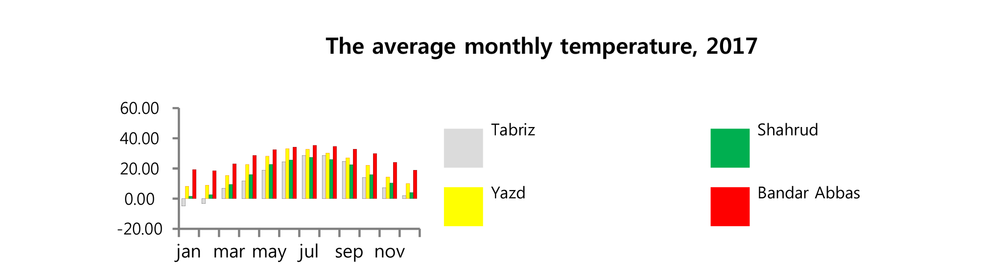
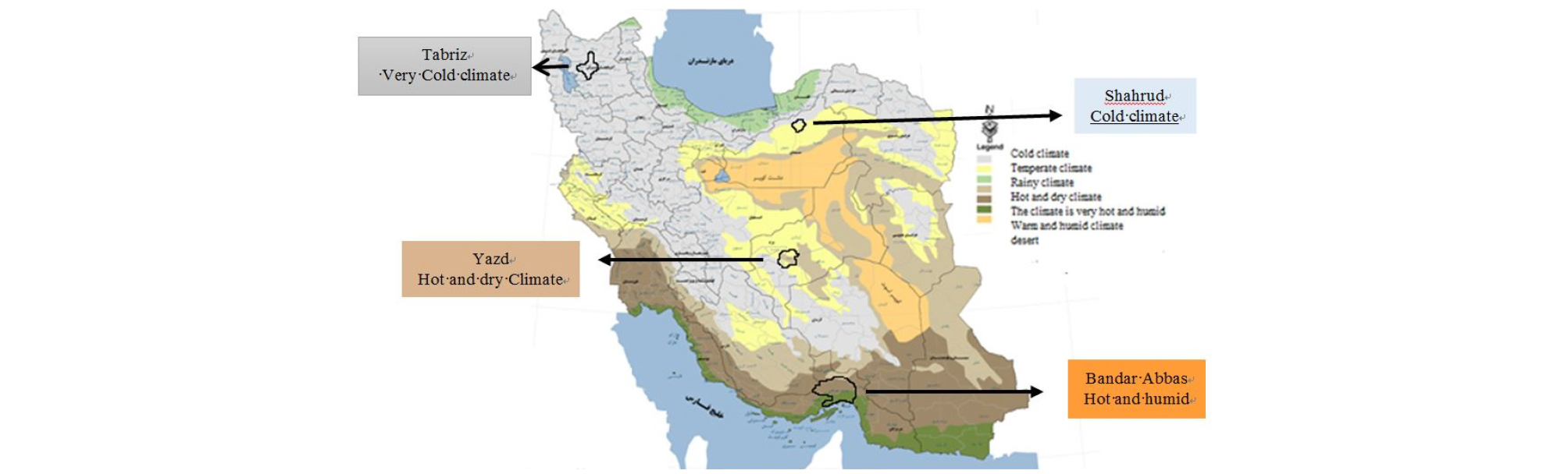
In this section, one representative of each climate in Iran was selected as a sample (Figure 3). They are as follows: Yazd was selected for a climate with hot and dry summers and cold winters. Bandar Abbas was selected for a climate with hot and humid summers and moderate winters. Shahrud was selected for a climate with moderate summer and cold winters, and, Tabriz was selected for a climate with moderate summers and very cold winters [23]. The average monthly temperature of 4 cities is in Appendix.
Yazd
With coordinates of 31°54’ 50” N and 54°17’ 4” E, with an elevation of 1230 m above the sea level, Yazd has an arid climate without any humid month and relative annual humidity of 30%, and, it is considered as an evident sample of arid climates. Yazd is located on yellow radiation belt and it is of high potential in terms of receiving solar energy [43]. In the country’s winter climate divisions, Yazd has a cold climate [23]. In a study conducted for a 10-year period (2008-2017), The highest average monthly temperature in July is reported 33.7°C, and, The lowest monthly temperature in January is 6°C [44].
To create thermal comfort in Yazd, first evaporation cooling, and then, heat absorption from inside the building are considered. Using these measures reduces active heating and cooling demands in this city [45].
Tabriz
Of climatic features of Tabriz are cold, hard and long winters, where for several months of the year, the grounds are covered with snow and ice. Tabriz is the capital of East Azerbaijan with coordinates of 46°25’ E and 38°02’ N, and an elevation of 1340 m above the sea level [23]. Precipitation is low in the summers, which is due to the west mountain range of Iran that acts as a barrier, prevents the penetration of the humid Mediterranean air into Iran, and preserve the humidity in them. Precipitation is as snow in the wintertime, and generally, a short spring divides summers and winters. By examining the temperature data of Tabriz, it is clear that 62% of the times the weather is cold and very cold, and, 17% of the times it is warm. The weather does not get very warm, and 27% of the times, it is moderate. The maximum mean temperature of the cold months in Tabriz is recorded for October, which is 14.55°C, and, the minimum mean temperature is recorded for January in Tabriz, which is -2.82°C [45]. In a study conducted for a 10-year period (2008-2017), the highest average monthly temperature in August is reported 28.3°C [46].
Shahrud
Shahrud is one of the counties of Semnan province and its largest one. It is located on the northern margins of Kavir Desert and southern skirts of Alborz mountains at latitude of 36°25’N and longitude of 54°58’E with about an altitude of 1380 m on the eastern north.
In the climate divisions, Shahrud has warm and dry summers and cold winters [23]. The governing wind direction in Shahrud is from northeast. Southwest and north wind directions are ranked next. The coldest month of winters in Shahrud is January, when the minimum temperature is -1°C. The highest temperature is recorded for July, which is 35°C. The average temperature of autumn and winter months, i.e. 8.9°C, is outside the comfort range. To ensure the comfort of residents, it is required to supply heat and employ solar energy [47].
Bandar Abbas
With coordinates of 27°13’ N and 56°22’ E, and an elevation of 10 m above the sea level [23], Bandar Abbas has a moderate cold weather in winters, and it is very hot and humid in the warm months of the year, which is an evident example of hot and humid climate. The average annual temperature in Bandar Abbas is 26.2°C. According to Olgi method, there is thermal comfort in Bandar Abbas in November, March and April. On October and May, air draft could be employed [48]. Among the cities under study, Bandar Abbas has the least thermal comfort hours in a year. In this city, there is a need for active cooling using mechanical devices, and, conditioning could not provide thermal comfort in this city [45]. Shading of the canopies are required for 26.3% during a year to obtain thermal comfort. In Bandar Abbas, February has the highest climatic comfort of 30%, and from June to August, there is no thermal comfort [45].
Employ solar energy in case of heating demand
In the climatic design of cold regions, it is a priority to employ solar energy (in case of heating demand). Tabriz, Yazd and Shahrud have cold winters, and, for the highest absorption of solar radiation through the walls, the mean angle of radiation from 10 a.m. to 2 p.m. (when the radiation angle is not oblique anymore) is the criteria to determine the wall angle of the building (Table 2).
Table 2. Average radiation angle in cold months in Yazd, Shahrud and Tabriz
Area of the Sample Temporary Housing
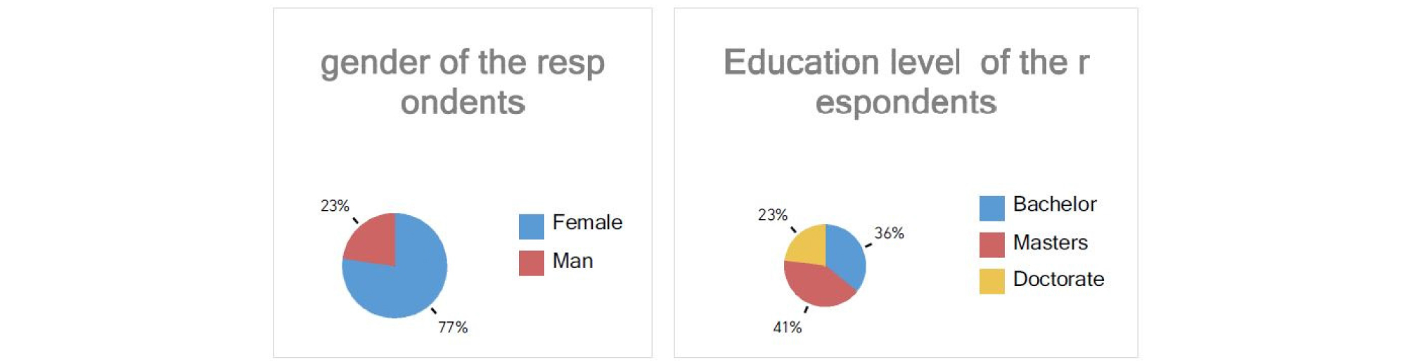
One of the reasons of users’ dissatisfaction is the temporary housing dimensions and the lack of living space requirements. Each housing must have a room, a small kitchen and a bathroom. According to the rankings in the brainstorming meetings and the Delphi method applications, the authors scrutinized the case, and ultimately, dimensions for the minimum area required for temporary housing were extracted according to the results that supply the survivors’ demands. The inventory used in Delphi method contained 6 items which was filled by 24 experts in architecture and building design. “Figure 4” show education level and gender details of these experts.
Using Microsoft Excel and AutoCAD, and according to Figure 5, the proposed area (minimum space) for temporary housing is shown in Table 3.
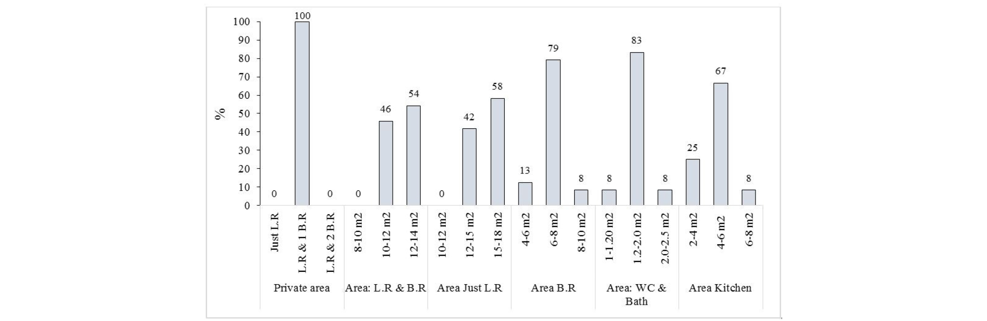
Table 3. Proposed area of temporary housing construction (Authors, 2018)
.jpg)
.jpg)
According to Table 3, the area of temporary housing should be at least 29-30 m2. If the plan is circular, a 3 m radius would supply the required space. According to Table 3, a 30 m2 area of temporary housing is considered.
The examined shapes to obtain the optimal shape of temporary housing
In order to study and optimize energy Demand of the temporary housings, regular geometrical shapes were selected to simulate the shape of the temporary housings (Table 4). Regarding that the temporary housing is a cell, there are limits to the size of its construction. The temporary housings are developing into special shapes. In Table 4, the investigated shape of temporary housing using regular geometrical shapes was introduced in 6 groups (cube, prism, pyramid, hemisphere and cone) and a group derived from the suggested shape by Nader Khalili1)[49]. Nine shapes examined in Table 4 had a height of 4 m, and 14 shapes of Table 5 had a height of 3 m. The shapes introduced in 5° were selected after being examined and selecting 9 primary shapes (Table 4).
Table 4. Energy Demand, usable area of the volumetric plan with a base wall of 1 meter (total height 4 meters)
.jpg)
.jpg)
.jpg)
.jpg)
.jpg)
.jpg)
.jpg)
.jpg)
.jpg)
.jpg)
.jpg)
.jpg)
.jpg)
.jpg)
.jpg)
.jpg)
.jpg)
.jpg)
Table 5. Energy Demand, Usable plan’s area in volumes without base wall (Total height 3 m)
.jpg)
.jpg)
.jpg)
.jpg)
.jpg)
.jpg)
.jpg)
.jpg)
.jpg)
.jpg)
.jpg)
.jpg)
.jpg)
.jpg)
.jpg)
.jpg)
.jpg)
.jpg)
.jpg)
.jpg)
.jpg)
.jpg)
.jpg)
.jpg)
1)Nader Khalili is one of the researchers in the field of temporary housing, who suggested making temporary housing using sand bags. The shape derived from the above suggestion was used in the present study.
Suitable Angle of the Walls of the Shapes
To determine the suitable angle of the walls, it is supposed that the highest solar radiation is absorbed from the south front, and, the wall is perpendicular to the radiation angle. Here, the angle of the south wall and the vertical axis are equal to the angle of radiation (Figure 6).

In pyramid and cone shapes, relying on the highest solar absorption by the walls, the mean angle of radiation from 10 a.m. to 2 p.m. in the winter months was measured (in Yazd, Shahrud and Tabriz) (Table 2). A 36° angle is the standard to select the angle of the wall with vertical axis (Table 2).
The Usable Area with Enough Headroom (in Terms of Height) in the Shapes under Study
The usable area of the plans in the shapes with sloped wall is of special importance (Figure 7).
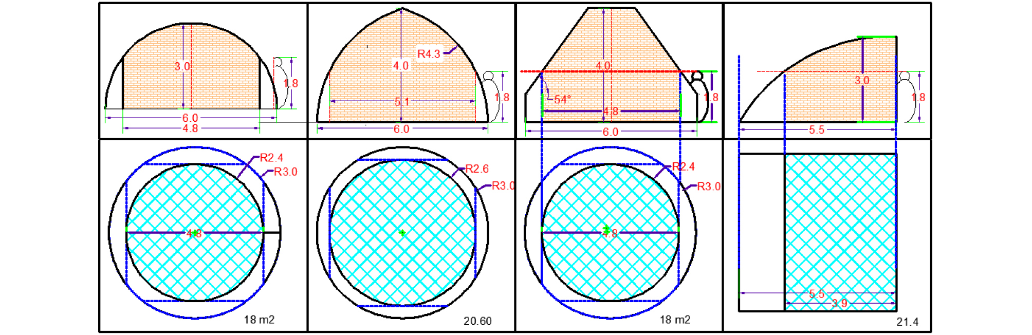
Making angle in the walls of the shapes (inclining the wall towards inside the building) restricts the use of the whole plan. To determine the usable area, a person with a height of 1.80 m should easily move inside the shape with enough headroom (up to the ceiling or inclined walls) while standing, and, this was considered in simulations.
Shapes with 1 m base wall (Total Height of 4 m)
The features of shapes under study, which are simulated to obtain the optimal shape for temporary housings are shown in Table 4.
If the height of sloped shapes is less than 4 m, the usable area diminishes. Therefore, the shapes with a 1 m base wall were investigated. For the base walls in the shapes with circular plan, adding a cylindrical shape with a radius of 3 m and a height of 1 m, and, in shapes with barrel vault, the base wall is a cube with dimensions of the plan and a height of 1 m, which is used as the base wall of the barrel vault (Table 4). In Table 4, the usable area of the plan considering the lack of headroom for the ceiling is shown in blue. The shape of a cone with a height of 3 m challenges the internal space. t create good internal space, in terms of having sufficient headroom, by creating a 1 m base wall for a hemisphere, a cross-section radius of 3 m, and a base wall with a height of 1 m, the total height will be 4 m.
Shapes without base wall (Total Height of 3 m)
When investigating the shapes with a height of 3 m, in addition to optimal energy Demand, the usable area of the plan in terms of having enough headroom is an important criterion to select an appropriate shape
In sloped shapes, the more the angle of the inclined ceiling relative to the vertical axis, the less the energy demand of the building. Therefore, an angle of 10 to 15° for sloped shapes was assessed. Although a cone with an angle of 20° has a lower energy Demand compared to a cone with an angle of 0° to 15°, its usable area is less than a hemisphere. Therefore, a cone with an angle of 15° is the selected shape to be compared to a hemisphere (Table 5).
Simulation Stages in DesignBuilder
Simulation of Shapes in Yazd:
‑ Spherical shapes; hemisphere with an area of about 30 m2 and a radius of 3 m with (and without) a 1-m base wall.
‑ Here, the temporary housing with a height of 3 m and 4 m, and a circular cross-section with a radius of 3 m was simulated (Table 4 and 5).
‑ Cubic shapes; the cross-section of the plan is about 5.5 m (an area of about 30 m2) in two heights of 3 and 4 m.
‑ Cylindrical shape; a circular cross-section (an area of about 30 m2) and a height of 3 m.
‑ Conical shapes (an area of about 30 m2 in the plan) in the heights of 3 and 4 m. A cone with a height of 3 m in 4 angles of the wall was simulated and investigated, namely 5°, 15°, 20°, and, 36° (relative to the vertical axis). A cone with a height of 4 m and an angle of 36° was simulated.
‑ Pyramid shapes with two cross-sections of hexagons and octagons (an area of about 30 m2) with the heights of 3 and 4 m and an angle of 36°.
‑ Prism shapes with two cross-sections of hexagons and octagons (an area of about 30 m2) with a height 4 m.
‑ Khalili shape with a height of 4 m and a circular plan (an area of about 30 m2) (inspired by a cottage shape with sand bags, suggested by Nader Khalili to build fast housing).
‑ After the simulation and comparison of the 1 to 7 shapes’ energy Demand in Yazd, the economic ones were simulated by DesignBuilder in other cities of the selected climates (Figure 8).
Analysis of Findings
The effect of the shape of temporary housing on energy Demand was investigated. Considering the hypothesis, energy Demand of the building could be reduced by changing the shape of the building without changing the area of the plan. To obtain an optimal shape for temporary housing, a building with lowest annual energy Demand is considered.
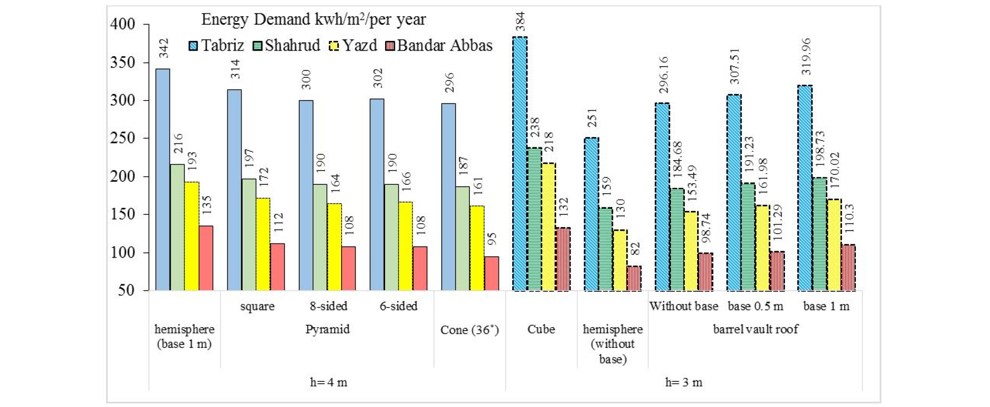
Investigating the energy required to build a temporary housing in shapes with a 1-meter base wall (total height of 4 m)
The energy Demand of various shapes for temporary housing with a height of 4 m is shown in Table 6. A cuboid shape with dimensions of 4 × 5.5 × 5.5 m in Yazd requires 289 kwh/m2 energy. Changing the shape of the building from a cuboid into a cone reduces annual energy consumption of the building for 44% (Table 6). Among the shapes investigated in this section, a 36° cone has the lowest, and the cuboid has the highest energy consumption. In a building with a height of 4 m, changing the shape from a cube into a hemisphere as well as prism and conical shapes reduces annual energy consumption of the building for average 40%. Reducing energy consumption by changing the cube shape into a prism is about 5%.
Table 6. The effect of volume change on the energy Demand of the building, an area of approximately 30 square meters, in Yazd
Investigating the energy required to build a temporary housing without base wall (total height of 3 m)
Then, the shape of a temporary building with a height of 3 m was investigated. Here, changing the shape of the temporary housing from a cube into a hemisphere reduces annual energy consumption for 40% (Table 7).
Table 7. Energy required for the construction of temporary housing in volumes without base wall (total height 3 meters) in Yazd
Although changing the cubic shape into a 36° cone leads to a 44% reduction in energy consumption (Table 6), due to the lack of sufficient headroom in a large part of the plan in this shape, a conical shape with a height of 3 m is not a priority to be selected for temporary housing (Table 5). Here, a cone with a wall angle of 10° (with vertical axis) to a wall angle of 20° was investigated. In case of selecting sloped shapes, a wall angle of 15°is suggested. However, the usable area of a cone is much less than a hemisphere. The usable area of a hemisphere is 18 m2, and the usable area of a 20° cone is 17.6 m2.
When changing the flat form of a cube ceiling into a barrel vault (without changing the height), heating, cooling and total energy consumption is reduced for 22%, 50%, and 29% respectively.
Selecting the Shape of Temporary Housing in Four Climates under Study
After investigating shapes with (and without) a base wall in Yazd climate (hot and dry) in the first simulation stage, the most economic models (in terms of energy Demand) for the second simulation stage, and the study of energy Demand in three cities (the representatives of three climates) were selected. The findings suggested that the energy Demand trend of the four climates is similar on the diagram. The hemisphere, prism and pyramid shapes reduce energy Demand more compared to other shapes. In addition, a building with square or rectangle plan and a barrel vault is a good choice for temporary housing. Although energy Demand of this building is more than a hemisphere, the usable area in plans with a barrel vault is more than hemispheres, prisms and conical shapes. To investigate the appropriate shapes in Tabriz, Bandar Abbas and Shahrud, the criteria was a 15° angle, because in the wall angles bigger than 15°, the usable area is small and inappropriate.
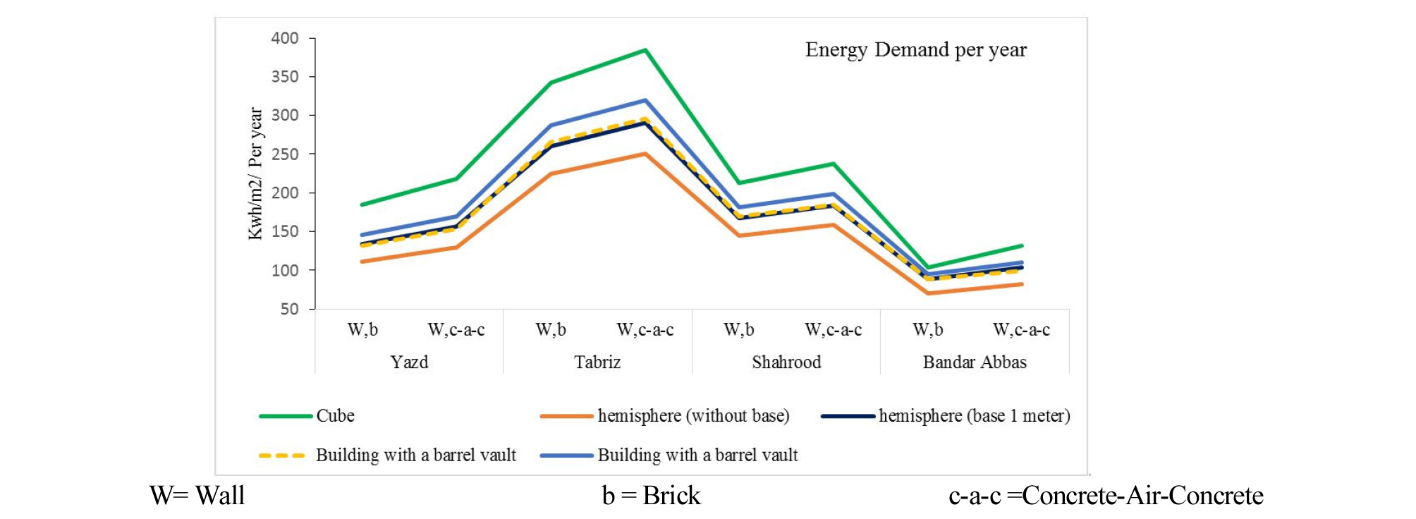
Findings show that: Compared to a cube, a hemisphere save energy by about 24 to 36% in each climate on average. When changing the flat form of a cube ceiling into a barrel vault, save energy by about 17 to 25% in each climate on average (Table 8).
Table 8. Percentage of energy saving in temporary housing as the shape changes from cube into other shapes: Hemisphere & Building with a barrel vault
Conclusion
This study was conducted with the aim of investigating the optimal shape of temporary housing and saving fossil fuel consumption (heating and cooling) in four cities, namely Yazd, Bandar Abas, Shahrud, and Tabriz. The study began with the following hypothesis: The form of the building influences energy saving, and, changing the shape of the temporary housing from a cube into shapes with sloped and curved walls reduces energy Demand of the temporary housing. The findings were assessed in two parts:
Part 1: A temporary housing in shapes with a base wall of 1 m (total height of 4 m).
Part 2: A temporary housing in shapes without base wall (total height of 3 m).
Results of the study confirmed the hypothesis. Findings show that: In a temporary housing without base wall (total height of 3 m), changing the shape from a cube into a hemisphere as well as prism and conical shapes reduces annual energy consumption of the building for average 40%. Compared to a cube, a hemisphere could save heating, cooling and total energy consumption for 33%, 57%, and 40% respectively. When changing the flat form of a cube ceiling into a barrel vault, heating, cooling and total energy consumption is reduced for 22%, 50%, and 29% respectively.
In order to compare different materials in terms of energy consumption, the intended shapes were simulated with brick and investigated. Given the similar movement trend of energy consumption diagram for different shapes, while changing materials, the use of proposed shapes was still valid (Figure 9).