

Introduction
Environmental and Socioeconomic issues
Steps in Brick-Making
Kinematics of machine
Design Consideration
Strength and Rigidity of Structural
Productivity
Size of the bricks
Ease of Operation and Maintenance
Design of Machine Components
Machine Frame
Mould (Die) Set
Punch Plate and Push Rod
The thickness of the plate is determined by
Mould Lifting Rods
Baseplate
Feeder
Pallet Transfer Mechanism
Actuation System
Conclusion and Discussion
Nomenclature
Wmax: Maximum Displacement
I: Mass moment of inertia
W: Displacement
B: Width of the punch plate
lx: Width of the base plate
t: Thickness of punch plate
ly: Height of the base plate
Wcr: Critical load
c1 c2: Constants
The cross-sectional area of the column
P: Pressure on the base plate
L: Length of column
H: Thickness of base plate
K: Radius of gyration
E: Modulus of elasticity
F: Axial force
W: distributed load intensity
D: Rod diameter
l: length of applied loading
Introduction
Currently, typical kiln technology only allows for a few numbers of material compositions, and this method also comes with several environmental and social issues [1, 2]. Materials like fly ash and concrete are growing in popularity as newer material compositions are discovered through research and tests. Bricks are sometimes also made from sludge and industrial waste materials from various operations. These bricks are often moulded into the required shapes. Compressing the raw material in a mould is one of the most crucial steps in the manufacture of such bricks because the attributes of the brick are mostly influenced by this process. The amount of energy used throughout this process is also substantial.
Wood, concrete, and earthen bricks have all been used in construction in the past. They will continue to be used in modern construction, which results in continuous resource extraction and deforestation [3]. When making bricks, cement is used to bond the sand and gravel together. To develop a better world, novel approaches, and sustainable and green building materials can be used. Materials like bamboo, corkscrew bales, mycelium accrete, lumber creation, etc. are frequently employed to achieve greater levels of sustainability.
Environmental and Socioeconomic issues
India’s unorganised brick industry is incredibly large and widespread. The brick business is expanding as a result of the towns’ and villages’ growing need for bricks as a result of the rapid development of the economy, urbanisation, and prosperity. It is discovered that brickmaking has not changed significantly through time or between different geographical regions. It is alarming to discover that 300 mm of India’s priceless topsoil will be consumed in about 60 years to make burnt clay bricks. As a result of soil erosion and deforestation caused by the production of red brick, the environment in the area is impacted. Due to the heat, soot, and smoke particles that are deposited on plant leaves during the production of red brick, plant respiration and photosynthesis may be hampered [1].
According to estimates, India is home to more than 100,000 brick kilns that produce over 250 billion bricks annually, employ over 15 million people, and burn about 35 million tonnes of coal, which is both an energy-intensive process and a potential source of air pollution. Brick kilns severely damage people’s health since they release a lot of hazardous pollutants [1]. The findings revealed that for every 1000 burned bricks produced, 4250 MJ of predicted embodied energy [4]. According to studies, harmful polluting gases like carbon dioxide, carbon monoxide (CO), chlorine (CL2), ammonia (NH3), Sulphur dioxide (SO2), nitrogen oxide (NO), hydrogen cyanide (HCN), and fluorine (F) can be released into the atmosphere as a result of the brick firing process. Depending on the type of kiln, fire period, technology, and fuel employed, these emissions have different concentrations [5].
Social issues like poverty, illiteracy, migration, and inadequate living conditions are also connected to the traditional brick industry due to the unorganised culture. The majority of brick-making procedures in kilns are carried out by employees who face incredibly hazardous working conditions, which can result in physical, biological, psychological, and ergonomic hazards.
Earthen bricks, concrete, and wood have all been employed in construction in the past and will continue to be employed in everyday construction which leads to continuous deforestation of timber and the extraction of resources. There are also been limited choices for materials that can be used for brick making through conventional kiln technology. To obtain more sustainability, various materials like bamboo, corkscrew bales mycelium accrete, timber create etc. are also been used often. Extensive research done on recycled wastes like concrete aggregates, granite waste powder, petroleum waste ash, crushed glass, polymers, and textile sludge and the effect of their proportion on the quality of the bricks is also been analysed [6, 7, 8, 9]. Production of bricks using various materials involves different process parameters. It is always difficult to incorporate versatility structurally and operationally [10, 11]. Mechanised brickmaking is becoming more and more popular in place of traditional kiln-based brickmaking to address social and environmental issues [12]. As a result, to create an optimal design, it is necessary to study the factors that affect the machine’s performance and design. The objective of this research is to develop a completely functional, hydraulically controlled machine for producing bricks in an environmentally friendly way. Brick manufacture that is automated can address regional infrastructure needs since it offers a range of climate-responsive materials [13, 14].
Steps in Brick-Making
The brick-making process includes sand preparation, compaction, and curing [15]. The sand is prepared in a specific quantity of sand, binders, and water. The composition of the ingredients have also a significant impact on the properties. The brick-making process can be described using the steps below as per Figure 1.
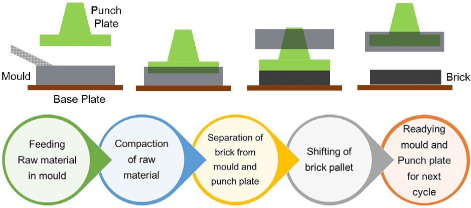
This mixture is fed into the mould box where it is compacted by the punch plate after being delivered to the hopper above the feeder [15, 16]. A robust foundation plate supports the wooden or plastic plates on top of which the mould is set. The mould can be made by hand, with manually operated equipment, or with completely automatic equipment. In the case of manually operated equipment, the compaction process is carried out by humans, whereas in the event of a mechanised process, the compaction pressure is applied mechanically [16]. The brick-loaded plates are pressed by a subsequent plate when the mould and punch are lifted. Extracted bricks are relocated to a new location to cure for 10 to 12 days in a humid atmosphere produced by spraying water onto brick stakes to acquire strength [17].
Kinematics of machine
The arrangement and flow of material have a significant impact on the overall performance of the machine in terms of cycle time, energy consumption, and operating ease [18]. The punch plate, mould box, and base plate motions must be optimised to minimise the overall production cost [19]. For the mould box, hopper, and punch plates, manufacturers use a variety of spatial configurations as shown in Figure 2.

The compressed bricks are extracted vertically or horizontally. The following are some of the most prevalent motion patterns.
a.Mould lifted and punch plate stationery,
b.Punch plate lifted and mould stationary.
A significant amount of force is required for compaction, which is supported by the machine’s frame and base plate. Base plates are fixed to the machine frame to ensure structural stability [20, 21]. As a result, the option of shifting the base plate is rarely selected over the other two alternatives. The lifting mould and punch plate alternative is utilised for the development of the machines stated in this paper because it facilitates the extraction of compacted brick from the base plate.
Material flow in various machines can occur as a crossflow or inline flow, beginning with the feeding of the raw mixture to the mould box and ending with the extraction of finished bricks after compaction. Because material cross-flow has no distinct advantage over inline flow, the majority of machines are designed for inline flow as shown in Figure 3.

Multiple mould boxes with single punch plates are also employed with a rotary table or inline flow configurations. As the structure must endure higher compaction pressure, which is challenging with a rotary table, such kinematics are preferred where the pressure requirement for the moulding process is very low. Very few brickmakers employ this moulding equipment as shown in Figure 4.

The punch plate, mould block, feeder, and wooden plate are all stimulated by actuators. Hydraulic, motorised, and pneumatically driven machines have recently been developed. Few devices are intended to convey motion using two actuation systems simultaneously. All operational sequences in hydraulic machines are controlled by operating individual valves or switches for each circuit, whereas in automatic machines, the motion is controlled by relays, timing switches or PLC-based controllers equipped with proximity and touch sensors [15, 22]. Compaction pressure, compaction time, velocity etc. are the most critical operating parameters.
An optimal set of parameters is determined for the specific raw material composition and desired quality of the bricks. The punch plate actuators’ capacity is determined with consideration of the maximum compaction pressure [23]. Similarly, system components are constructed with the calculated operating parameters for the desired capacity in consideration [11, 24].
Design Consideration
The requirement for force during the compaction process emphasises the design of fully automatic equipment. Brick compression is acknowledged as being the most crucial operation in terms of energy consumption and produced stress in structural components [25]. Different machine configurations are investigated, and the optimal option is chosen based on operating simplicity and ergonomic design elements [26]. The dimensions of machine parts were calculated through simulation and strength-based design calculations. When designing the machine, a few key factors including structural strength, rigidity, productivity, brick size, ease of operation and maintenance, safety, cost, etc. were taken into account. Compaction pressure is thought to be an influencing factor that determines the important components of the machine’s major dimensions.
Strength and Rigidity of Structural
All of the machine parts are mechanically supported by the structure, which functions as a framework. The worktable, slide, column, and base of the machine are all essential parts [26]. The most important aspects to take into account while designing and choosing a machine are structural configuration, stiffness, damping, structural connection, interface, structure dynamics, and associated performance [27].
High structural response, greater damping characteristics, an asymmetrical and closed-loop structural arrangement, long-term stability, and isolation from environmental influences should all be goals of robust mechanical structure design [11]. Another important factor that affects machine performance is the material. While polymer concrete has gained favour for ultra-precision machine tools needing lightweight, high damping capacity, and rigidity cast iron and granite have traditionally been utilised for machine bases and supports [18, 28, 29].
Productivity
The number of units produced of the resources consumed is typically how production efficiency is calculated. The quantity of units produced over a predetermined period and power consumption can likewise be used to quantify a machine’s efficiency. It may also be seriously considered to limit the overall cost of the machine and production to incorporate additional costs by using expensive and complex modules to increase the output rate.
Size of the bricks
For fly ash and burnt clay brick, the Bureau of Indian Standards (BIS) recommends employing bricks that measure 225 mm × 102 mm × 75 mm [30]. Fly ash and burnt clay bricks are utilised as standard sizes for designing machine parts since they are the most prevalent and well-liked bricks used in home construction. For certain construction needs, there are several customised sizes available.
Ease of Operation and Maintenance
Although the majority of this study has focused on designing completely automatic machines, human participation is still important since handling materials before and after production requires careful consideration of many ergonomic issues [24]. A minimum changeover time that cuts down on downtime was always wanted. Maintenance is made simpler by modular design [24].
Design of Machine Components
Design calculations for all the structural components were carried out using strength-based empirical relations and for critical components, dimensions were verified through FEA. A few of the FEA plots are depicted in Figure 5. Key components of the machine like the Baseplate, Mould (Die) set, Punch Plate and Pushrod, Machine frame, Mould lifting rods, Feeder, Hopper, Pallet transfer mechanism etc. were designed as follows.

Machine Frame
The brick moulding process exerts significant forces on the frame. Both static and dynamic loads are applied to the frame. The frame will support a dead load of Baseplate, Mould set, Punch plate and push road assembly, Hopper, Guide rods, Pallet with finished Bricks, and cylinder assembly.
The frame also needs to support the dynamic forces generated during compaction, feeding, pallet transfer and uplifting of the mould set.
The kinematic layout of a machine frame is determined in the first stage of design. The kinematic layout is finalised after a rigidity and stability comparison among the various alternatives. As a result, the frame was designed with the long-column theory consideration. Euler’s formula applies to long columns [31].
Mould (Die) Set
Based on the shape, size, and several bricks to be moulded in a single stroke, a variety of moulds can be built. A modular design of the mould set is preferred to accommodate the changing shape and size requirements of the bricks. The design method in this paper, however, is done for typical brick sizes recommended by IS 1077 (1992) and 2 x 1 Die.
The mould size was determined by the size of the brick to be produced and the amount of clay mix required to produce such a brick.
Standard Brick Dimensions = 225 mm × 105 mm × 75 mm
The overall dimension of the mould set is to be determined by adding the thickness of the outer plate and partition plates.
The thickness of the Outer plates and partition plates wall is calculated considering uniformly distributed load over the entire length and allowable minimum deflection of the plate [32, 33].
From the results of the calculation above, the allowable mould thickness = 16 mm
Punch Plate and Push Rod
A push rod is designed as a short column under compressive load. The push road length can be determined by taking the geometrical measurements of the mould height, feeder height, and stroke length into account. The punch plate is attached at the bottom end, enabling compaction force to be applied to the raw material in the mould. The length and width of the punch plate match the dimensions of the die set. Some clearance is always allowed on both sides for ease of removal from the mould.
The thickness of the plate is determined by
Mould Lifting Rods
The mould is lifted when the compaction process is complete so that the produced brick can be transported farther. The plunger of minor cylinder 1 is connected to a C-shaped rod. Axial load is applied to both rods. The weight of the mould set and the separation force between the mould walls and the bricks are used to compute the overall load operating on the lifting rods.
Baseplate
Mould boxes must be securely supported on the base plate and able to withstand the force of compression used during the moulding process. The base plate is always kept detachable to achieve versatility in the design [12, 34].
The base plate is subjected to a compressive load over the surface and has been supported by three stiffeners fixed to the base plate supported by the machine frame.
Feeder
The feeder is designed to hold the volume that will be processed through each cycle. The mix is mostly poured into the mould cavity by the feeder. The feeder is made up of a single hollow cavity the size of a rectangle into which the mixture is fed from the hopper and poured into the cavity of the mould using a to-and-fro motion over the top of the mould. This motion is transmitted by a minor cylinder 2. The criteria for establishing the height of the feeder box depend on the plunger stroke length of Major Cylinder 1. Since a feeder does not experience heavy loads, so rectangular mild steel box of 5 mm thick sheet compatible with the mould dimensions.
Pallet Transfer Mechanism
On the machine frame, wooden pallets are piled. A push rod powered by cylinder 3 is used to push the loaded pallet when one cycle of operations is complete. The force is necessary to lift the bricks placed on the pallet and get rid of the friction between the pallet and the base plate. Solid flat base plates are generally used in all machines. for this research work a novel transfer mechanism has been developed, in which cavities are provided at uniform distances to accommodate roller-fastened helical springs. During the compaction process, the spring is compressed; after the process is over, the spring begins to regain its length, elevating the rollers just slightly above the surface of the base plate [35]. The wooden tray containing ready bricks is pushed by the other empty tray as shown in Figure 6.

Power consumption is evaluated using the proposed mechanisms, a solid roller conveyor and a helical compression spring mounted on rollers. The entire system is made up of a travel mechanism and a removable base plate.
Actuation System
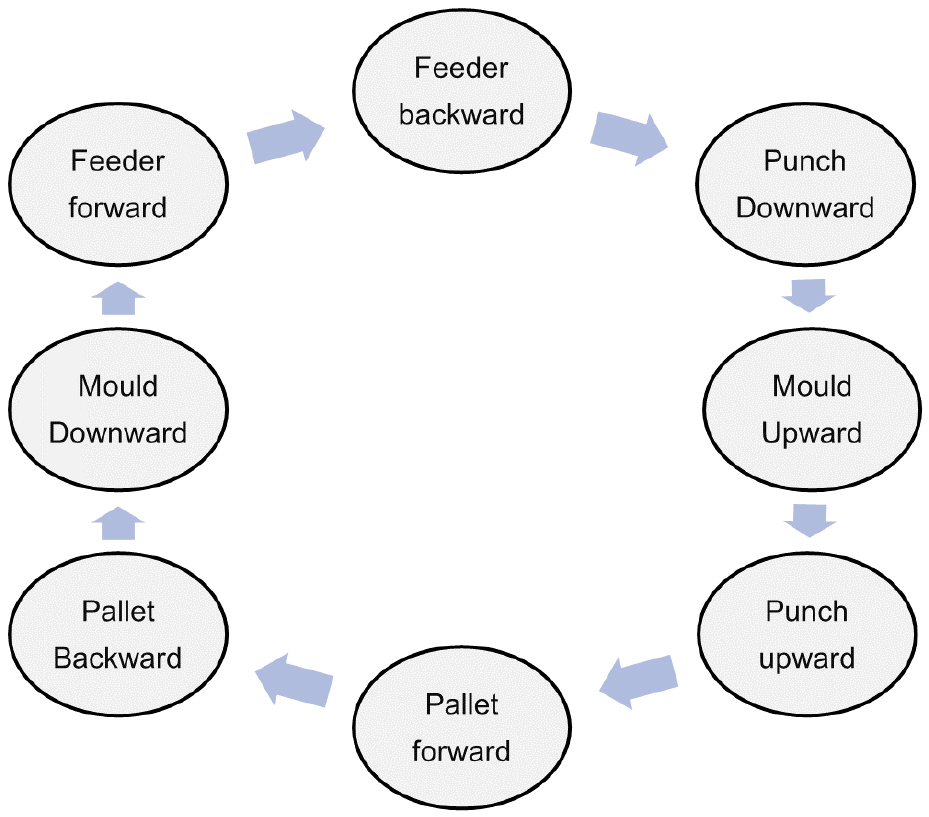
The relative motion of various machine parts is involved in the process of producing bricks on a machine [20, 22, 36]. This list contains all of the motions that occur during the process and their sequence are also depicted in Figure 7.
1.Feeder’s back-and-forth motion from the home position to mould
2.The to-and-fro action of the punch plate from the home position to the mould
3.The to-and-fro motion of the mould from the base plate to the top position
4.Completed block loaded tray to conveyer; empty tray behind punch plate
One of the most important factors is choosing an actuation system because it has a significant effect on cycle time, functionality, coordination of operations, and eventually machine performance. Although a few combinations of different actuation technologies are also employed, the majority of manufacturers use hydraulic actuation for all four motions. In these systems, the motion imparted to the brick trays is motorised while the other three motions are imparted hydraulically [24, 36]. The use of several controllers and sensors is required when using different actuation systems in one machine, which adds to the system’s complexity [37]. Mixed actuations (hydraulic + motorised) do exist in industries, though.
Hydraulic actuation, in which a hydraulic power pack is fitted and dedicated hose lines connect all four cylinders, is frequently utilised for all four fundamental motions. All lines are used to feed the cylinders with compressed oil, while particular lines are used to move the plunger (Figure 8). The power pack’s pressure and the amount of oil being pumped determine how quickly the plungers move. The force required for the operation determines the pressure required in each of the four hydraulic circuits. The overall hydraulic system’s capacity is defined by the pressure needed in compaction because this operation requires more pressure than the other three processes do. The amount of raw material affects how long it takes to condense.

For the research work, a hydraulically operated fully automatic machine with the capacity of producing two bricks per cycle is developed. Hydraulic circuits in these machines are equipped with solenoid valves and pressure-regulating valves to control oil flow and pressure (Figure 9). The control circuit is developed by employing relays and limit switches to obtain the sequence and adjust the operational time for each process.

Conclusion and Discussion
The pace of brick production is rising daily to meet the infrastructural needs. Conventional kiln-based production of bricks resulted in a rise in the creation of hazardous emissions that are harmful to society, and the environment. As an unorganised sector, conventional brick making carries issues like insecure minimum wages, non-suitable physical environment at work, long working hours, health and occupational risks, insecurity resulting from illness, failure to enforce social security measures, poverty and Debt, job insecurity etc. Therefore, it was deemed crucial to create new methods and technologies in order to reduce the detrimental consequences on society, the environment, the economy, and human health.
Dimensions of all the major machine components were determined on the strength and stiffness basis. To optimise the design of all machine components, numerical analysis is used. The fundamental three aspects: rigidity, robustness, and flexibility in design were pre-approved throughout the entire process from idea to machine manufacture. Spatial kinematics was obtained by optimising the travel of moving parts and ergonomic considerations. An easier mould-change arrangement is incorporated to mould a variety of construction bricks in terms of shape and size. Velocities of all the cylinders are controlled by adjusting the flow of oil using a flow control valve. Because of its versatility in parameter management under different working situations, the machine is more versatile in terms of material composition and ingredients for brick manufacturing.
Simplified modular technology integration enables increased productivity, scalability, and customisation, which potentially results in saving consumers money. It also allows for the adaptability of varied consumer demands in a continually changing market and technological advancements. To further optimise the process, newer actuation or mechanisms can be designed to combine operations [21].
As far as The operating cost has a major effect the economic efficiency, a newly developed Pallet Transfer Mechanism with roller mounted helical spring enable the energy economy compared to the flat base . The developed machine can produce two bricks in a cycle. The operating cost of the developed hydraulic machine was compared with the claimed economic efficiency of similar machines used at large scale.
