

Introduction
General Methodology for Forensic Investigation
General forensic investigation Procedure
Problem Statement
Construction procedure for Head wall
Forensic Investigation
Field Observations and Testing
Failure hypothesis
Observation from the Forensic Investigation
Numerical Analysis
Suggested Remedial Measures
Encasing of Hume pipe
Providing a thick base to the Hume pipe
Increasing the compaction of the subgrade soil
Conclusion
Introduction
Pipe culverts, made from steel, concrete or high-density polyethylene, are hydraulic structures installed in trenches or embankment configuration, are primarily used for providing passage to storm water from one side to another on a road way or beneath it in hilly region [1]. These pipe culverts are considered as an important component of any road or highway projects as they provide safety against floods and reduce the chance of any unforeseen circumstances that may restrict the traffic movements and increase the risk towards accidents or public safety as well as damage to economy. In recent years, it has been observed that majority of the pipe culverts show sign of distress or sometimes ultimate failure during extreme rain or flood conditions. Reason being combination of various factors, such as, settlement due to unstable ground, scour and erosion of the in situ soil beneath the culvert and additional hydrostatic pressure due to saturation or submergence [2]. Additional factors include aging effect, deterioration of the pipe material due to abrasion, corrosion and other environmental factors [3]. Debris and sediment deposits also cause clogging of drainage channel and subsequent failure [4, 5].
Forensic Engineering is application of engineering principles and methodologies to analyze the failure and provide subjective evidence for litigation support and fixing the liabilities. Forensic Geotechnical Engineering is a process which involves engineering, legal and scientific investigations and methods to detect the reasons of failure and process of development of sign of distress, failure and collapse in a structure, which may be caused due to geotechnical reasons. Several case studies [6-9], which have been taken up earlier for such forensic investigation in various aspects and reason of failure cases and its remedial measures which have been found very effective with regards to economy and legalistic scrutiny also fall in same purview. Studies show that application of Bayesian networks in forensic engineering helps in the analysis of technical causes of a catastrophic bridge downfall [10]. Moreover damage in building occurs during nearby construction can be analyzed through forensic analysis [11].
In majority of case studies, it has been reported that the standard procedures which are adopted in routine testing, design and analysis are not adequate rather the test parameters, design parameters and basis of analysis will have to be in similar condition encountered at site. The scope for forensic investigation covers the following: (i) To investigate the initial reasons behind failure and establish an initial theory of failure, (ii) collection of the evidences in support of theory adopted for failure, (iii) selection of suitable testing methods and techniques to prove the evidence collection in support of failure scientifically, and (iv) To reach out at the conclusion of final reason of failure and derive the basic cause of failure based on the analysis of evidence. The objective of the present study is provide a brief understanding of the forensic investigation procedure and its implementation in one of the case studies encountered during the construction of Hume pipe culvert when series of cracks were observed in majority of culverts constructed on a major national highway in India.
General Methodology for Forensic Investigation
General forensic investigation Procedure
Normally, investigations are carried out into four stages, i.e., the early stage, evidence collection stage, analysis and confirmation of failure assumption (hypothesis) and conclusion stage.
Early stage of investigation
The investigation process maybe started based on assumed initial failure theory or hypothesis. After establishing the initial failure hypothesis, investigation approach to collect evidences and confirmation of failure hypothesis must be planned. The testing techniques and associated equipment useful in evidence collection are identified during this stage.
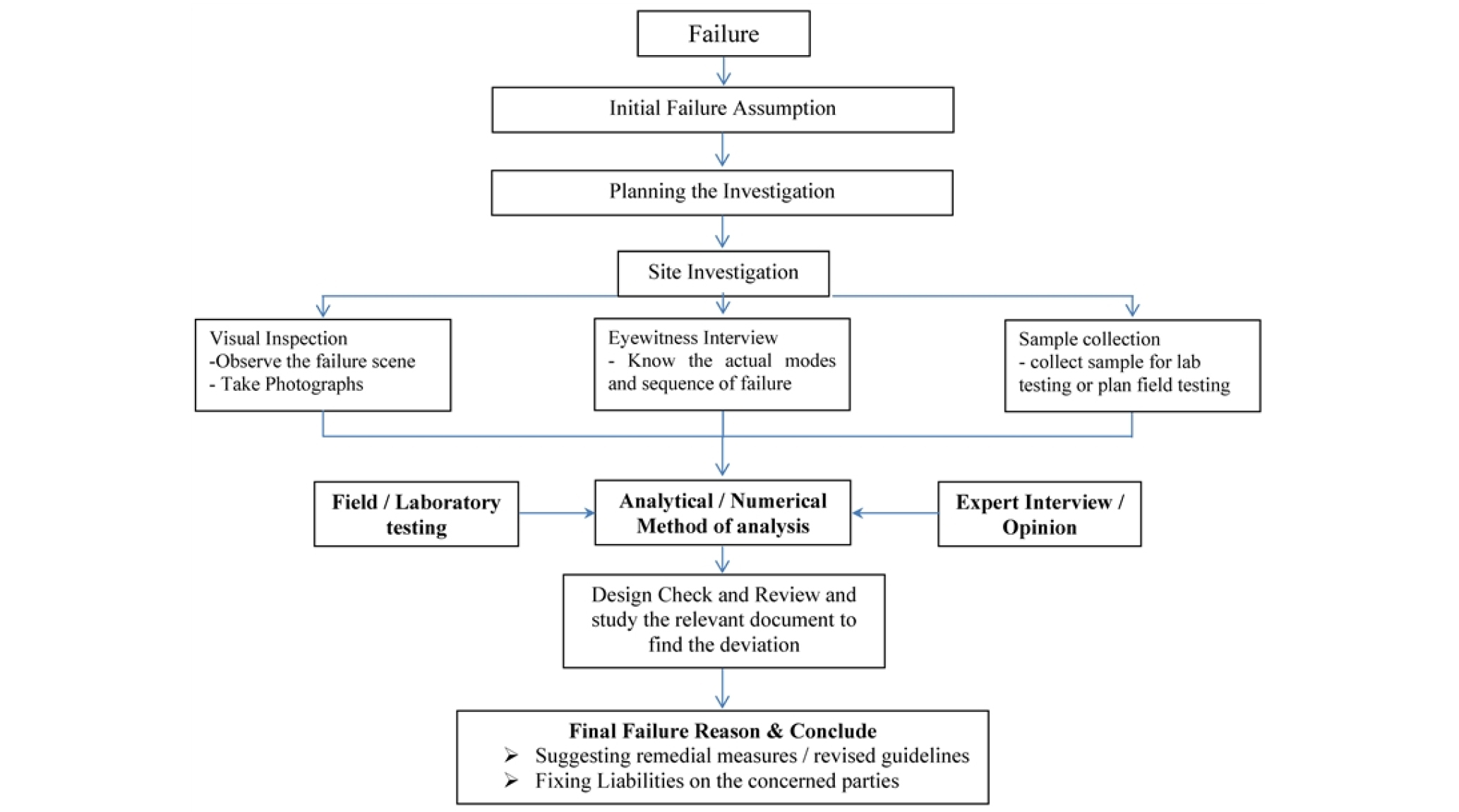
Evidence collection stage
Reaching the failure site as soon as possible after the failure happened to avoid any disturbance to the evidence. Early start of site investigation is very useful and necessary in investigation approach which comprises of visual inspection, eyewitness interviews and sample collection. By visual inspection, investigators can observe the failure scene and wreckage and take its photographs which may provide the main evidence of failure. By eyewitness interviews-eyewitness often provide the valuable evidence and feedback to investigators which are helpful in deciding the actual modes and sequence of failure. Collecting the samples is an important step in the evidence collection stage for analysis.
Analysis and confirmation of failure hypothesis
There are three approaches of analysis and confirmation of failure hypothesis by carrying out testing methods, analytical methods and expert’s interviews.
1. The testing methods consist of field testing and laboratory testing. Field testing involves a series of non-destructive testing and destructive testing carried out at site to check the actual behavior of the structure. Laboratory testing involves some specific tests that are normally destructive tests to check specific properties of certain components of structure.
2. Analytical or numerical methods comprises of design check and computational analysis. Design check includes the review of relevant documents related to the failure. Computational analysis is an approach by using computer engineering software to compute and analyze the case study.
3. A supplementary approach to analyze the failure hypothesis is by means of expert’s interviews. Normally an expert’s opinion can be very valuable to the investigators to understand the cause of the failure.
Conclusion stage
Last stage is the conclusion stage when all the analysis work has been done and failure hypothesis is confirmed.
Following Figure 1 depicts the systemic approach for the forensic investigation which is followed in the present case study, i.e., failure analysis of Hume pipe culvert head wall.
Problem Statement
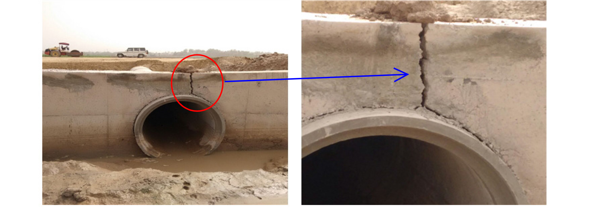
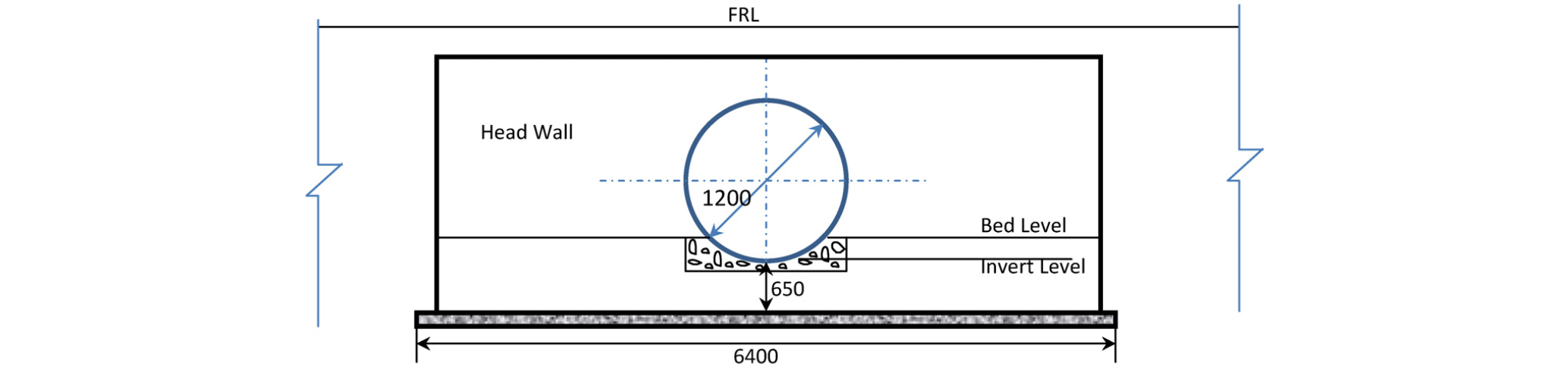
For cross drainage of accumulated water from upstream side (U/S) to downstream side (D/S) of one of the National Highways (NH), a 1200 mm diameter Hume Pipe Culvert (HPC) was proposed on a bypass. The construction of Hume pipe culvert was considered as the part work of Four Laning & strengthening of the national highway. For protection against the scouring or undermining of fill or a flow diverting device of HPC, headwall is generally constructed to confine the road laterally at two ends of culvert and also serve as a retaining wall. As per information and records, the construction of these culvert started in the month of June 2016 and was completed by the mid of July 2016. Soon after the construction, cracks were visible in the month of August 2016 during inspection. Similar observations were made at several other locations and severity of these cracks was increasing and with time and gradually the crack reached width of 5mm to 10mm within a span of one month (Figure 2). Figure 3 shows typical geometrical details of Hume pipe culvert. To determine the reason and remedial method for this problem was a serious concern to the technical team involved in the construction.
Construction procedure for Head wall
Construction of HPC follows the sequence of activities like preparation of bed of foundation soil, specifically, leveling and compaction of the soil bed. The soil bed is generally compacted to a specified standard using mechanical equipment like, rollers, vibrators or rammers or manually. After desired soil bed compaction, a plain cement concrete (PCC, Grade – M10) of approximately 100 mm thickness was built as a foundation concrete support for the Hume pipe. To avoid any type of leakage in Hume Pipes, (fume test) they were laid and jointed with each other (Figure 4). After joining of the Hume pipes, headwalls were constructed on both ends of culvert, to serve as a retaining wall.


For a concrete or masonry headwall, sign of failure at early stage is very rare. However, if cracks are visible at very early stage at a particular position of headwall, forensic investigation should be performed to estimate the reason of early stage failure and to provide remedial solution.
Forensic Investigation
Field Observations and Testing
Settlement of head wall and Hume pipe culvert was monitored during and after construction and it was observed that significant amount of settlement was noticed within a month of casting of head wall. It was also noted that there was intermittent rain soon after construction (within 15 days) of culvert and the foundation soil was submerged under water (Figure 2). As per drawing, the top R.L. of Head wall should be kept at 209.370 m (when head wall was casted). Reduced Level at different locations of head wall were measured (Figure 5a) and has been reported in the Table 1. The soil sample was collected from the site and tested in laboratory for various parameters (Figure 5b). Sand replacement method was used to estimate the in situ density of the field soil (Figure 5c). The site was thoroughly surveyed for any construction deficiency (Figure 5d).


Table 1. Reduced Level (meter) of Head wall
| Side | Towards H | Center | Towards S | Average |
| LHS | 209.337 | 209.272 | 209.314 | 209.307 |
| RHS | 209.178 | 209.095 | 209.148 | 209.140 |
Note: Top level (Reduced Level in meter) of Head wall as per drawing = 209.370
It can be observed that RHS of head wall settled more as compared to the LHS of headwall, however, the settlement was uniform. On the LHS, the amount of differential settlement was 0.065 m(209.337-209.272) and 0.042m (209.314-209.272) on both side of the culvert. Similarly, on the RHS, the amount of differential settlement was observed to be 0.083 m(209.178-209.095) and 0.053m(209.148-209.095) on both side of the culvert. This might have caused stress concentration at the location in head wall and cracks were developed. Total amount of settlement from the original RL (209.37 m) of the head wall was estimated as 0.063 m, i.e., 63 mm (LHS) and 0.230 m, i.e., 230 mm on the RHS.
Failure hypothesis
Based on the expert opinion and review of documents, following were the possibilities of failure and further investigated was suggested:
a) Swelling and shrinkage of the field soil
b) Excessive settlement due to improper compaction of foundation bed
c) Lateral earth pressure due to filling of material inside
d) Construction or design deficiencies
Swelling and shrinkage characteristic
Soil samples were collected from the both side of Hume pipe culvert below head wall (Figure 5b) and its properties like grain size analysis, Atterberg’s limit and free swell Index and compaction characteristics have been checked in site laboratory. Table 2 summarizes geotechnical properties of the field soil.
Table 2. Geotechnical properties of soil
| Geotechnical Properties | Location - A (LHS) | Location - B (RHS) |
| % Gravel | 10.0 | 11.5 |
| % Sand | 22.5 | 22.7 |
| % Silt & Clay | 77.4 | 76.1 |
| Liquid Limit | 24.8 | 21.9 |
| Free Swell Index | 18.2 | 19.8 |
| OMC | 11.3% | 11.3% |
| MDD | 1.88 gm/cc | gm/cc |
Field Density
Field density of the soil was determined through sand replacement test (IS: 2720-Part (XXVIII) and was conducted at site near to foundation of headwall. Table 3 summarizes the results of the field density test.
It can be observed from here that the soil was very well compacted on the LHS of the culvert and the relative compaction (RC) value of more than 95% was achieved and hence settlement of the LHS of the culvert was less. However, soil on the RHS of the culvert was poorly compacted and RC of only 85% was achieved which might have caused excessive settlement of the head wall. The amount of settlement has been estimated from the following formula (Eq. 1).
𝛥H = 𝛥e/(1+eo) ×Ho (1)
where, 𝛥e = change in void ratio = (ei – ef)
ei = initial void ratio and ef = final void ratio
Dry unit weight of the in situ field soil after compaction = 1.88 × 0.85 = 1.598 gm/cc
Assuming Gs = 2.65, the initial void ratio is estimated as, 0.66
Assuming that the soil gets further compacted due to load of head wall and it achieves a dry density of 1.73 gm/cc (field observation), final void ratio is estimated as, 0.53
Hence, 𝛥e = 0.13
The base width of the head wall = 1.25 m. Assuming zone of influence as 2.0B, the amount of settlement was estimated as
𝛥H = 0.13 × 1.25 × 2 / (1+0.66) = 0.195, i.e., 195 mm
It can be noted that the total amount of settlement observed on the RHS of the culvert was 222 mm, and the calculated value of settlement is found to be 195 mm. Thus the settlement is found to be comparable from both the methods.
Table 3. Field density of soil
Possibilities of any construction or design deficiencies
There were number of construction deficiencies observed at site, most importantly was that the overall construction procedure was done in a speedy manner and sufficient time for each activity has not been provided on site. Some of the issues have been summarized below:
a) Original ground level was not properly compacted before laying the PCC bed, which results in less bearing capacity of the soil.
b) The PCC of the bed foundation was laid and appropriate curing time (Min 7 days) was not provided and next course of concrete work was started (laying and joining of pipes and head wall). Hence the PCC could not achieve the desired strength.
Observation from the Forensic Investigation
Critical analysis of all possible causes of failure resulted in the assumption of the most significant causes which are as follows:
∙ The assumption that foundation of head wall was resting on black cotton soil due to which swelling and shrinkage cracks were developed has not been found correct as free swell index (FSI) of soil was less than 50. FSI of soil sample of both end of H.P.C. head wall was found around 18% & 19% and liquid limit was also less than specified for unsuitable soil. Hence, the tested soil property does not support the assumption and the soil although had blackish appearance does not possess the swelling and shrinkage properties.
∙ The assumption of lateral movement of the wall was also not been supported by field observations as there was no lateral displacement noticed in head wall. Also, the space between headwall was not filled with soil and thus no lateral pressure was developed which could have resulted into failure cracks. However, the road way was filled with soil on later stage of road construction after the cracks appeared.
∙ The hypothesis of improper compaction was also checked and it was found that the RC value achieved in the field was approximately 85%, which was much less than the specified value of 95%. Hence, there was improper compaction at the site. After the construction of head wall, soil settled to due huge pressure of head wall and resulted into cracks at the crown of the Hume pipe.
∙ By eye witness interview, it has been brought to notice that there was no proper compaction below foundation of headwall and the construction of head wall was done in a hasty manner. There was no enough time gap between casting of leveling course (P.C.C.-M15) and raft of headwall. It was also noticed (Figure 5d) that P.C.C. below Hume pipe connecting to raft of head wall was also not laid with proper compaction.
∙ Based on all these observation, numerical analysis of the stated problem has been performed to observe the stress development and failure and further the remedial measurement have been suggested and been verified through numerical analysis.
Numerical Analysis
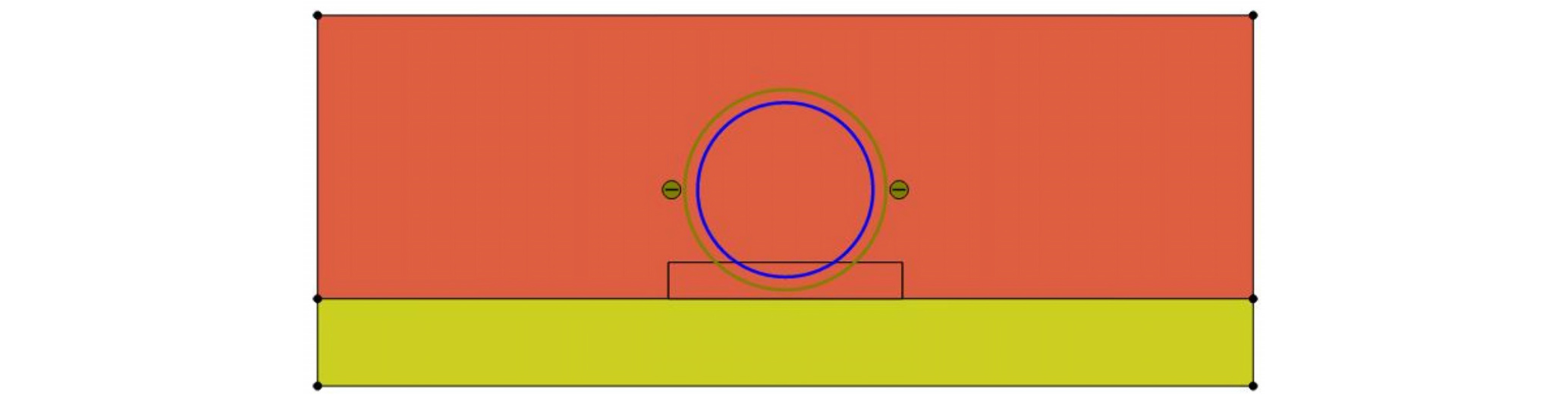
Commercially available Finite element tool PLAXIS 2D was used to perform the numerical analysis of the present problem. 15-noded triangular elements can be used for generating finite element mesh. Soil behavior was modeled as to follow the Mohr-Coulomb failure criterion. Tunnel element was used to the Hume pipe. Concrete Head wall was considered as elastic material with properties of M15 grade. The input properties used for the numerical analysis are summarized in Table 4.
Table 4. Input properties for the numerical analysis
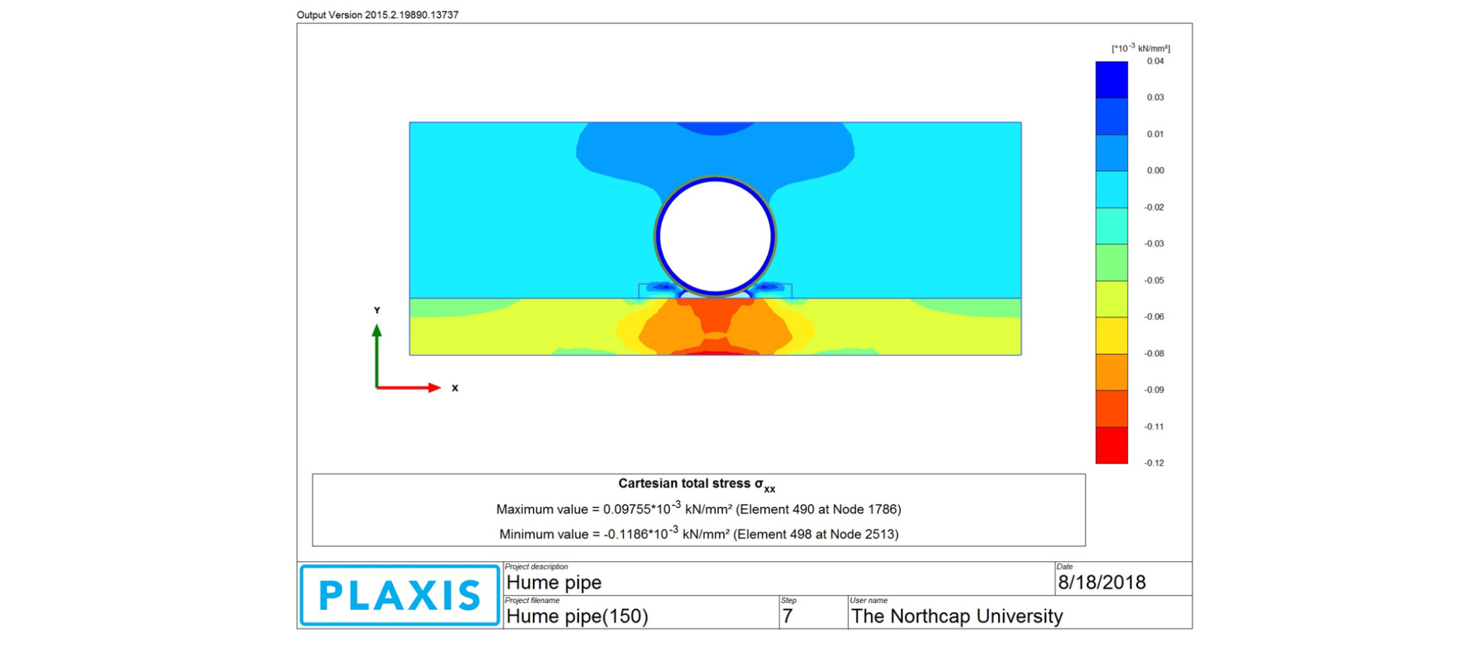
Figure 6 (a and b) shows the step followed in the numerical analysis of the Hume pipe culvert. From results of the analysis, it can be noted that both compressive and tensile stresses are developed in the head wall. Blue shade shows tensile stresses developed and red shades indicates development of compressive stresses in the Head wall. It can be noted that the tensile stresses developed in the head wall is at the location of the crown of Hume pipe where the crack was developed. As we know that concrete cannot take tension, development of tensile stress (97 kN/m2) has caused severe cracks in the head wall.
Suggested Remedial Measures
Based on the failure investigation, the following remedial methods are been suggested:
Encasing of Hume pipe
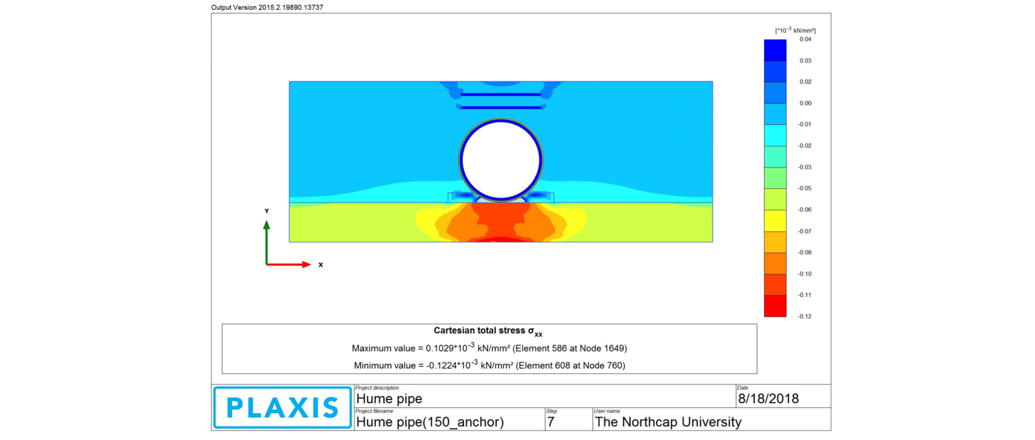
The FEM analysis of the existing head wall shows the development of tension zone at the top of the Hume pipe, which is responsible of cracks in the pipe (Figure 6b). Hence, it is suggested to provide nominal reinforcement (8 diameter @150 c/c) at the crown of headwall to increase its resistance against tensile forces. Figure 7.1 shows that when steel reinforcement is being provided the stress concentration has been reduced significantly.
Providing a thick base to the Hume pipe
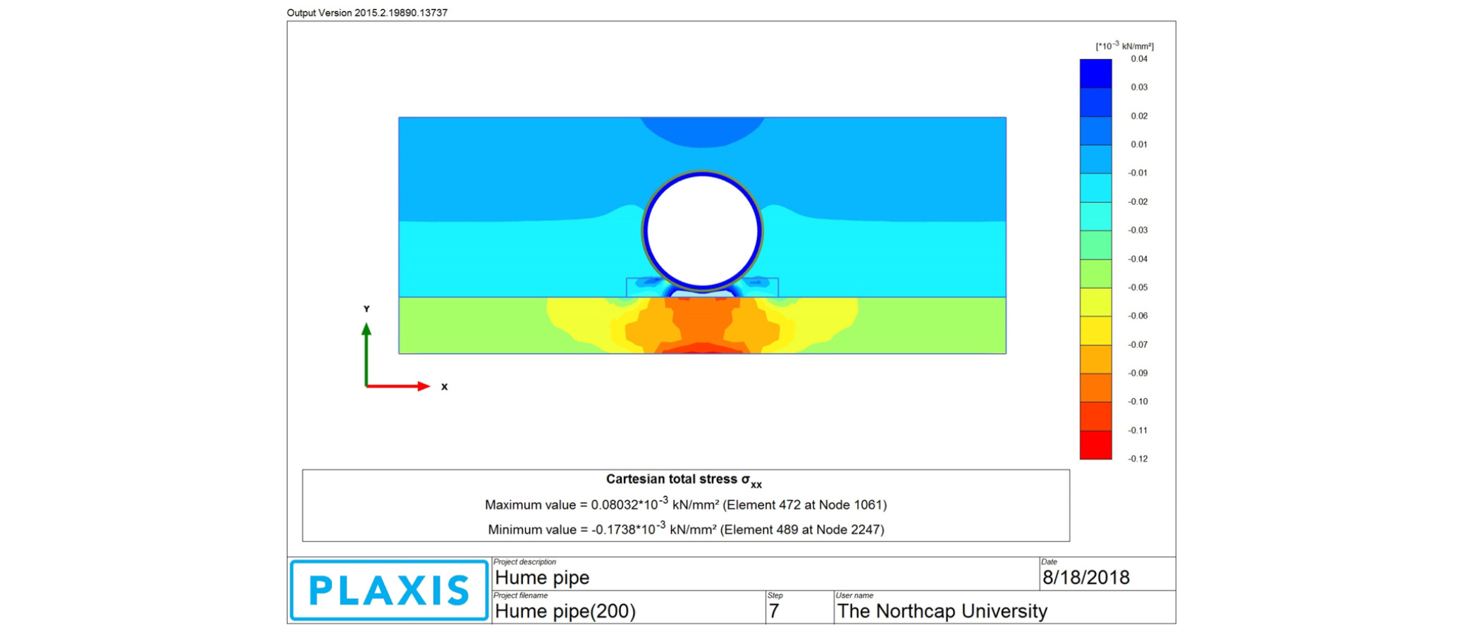
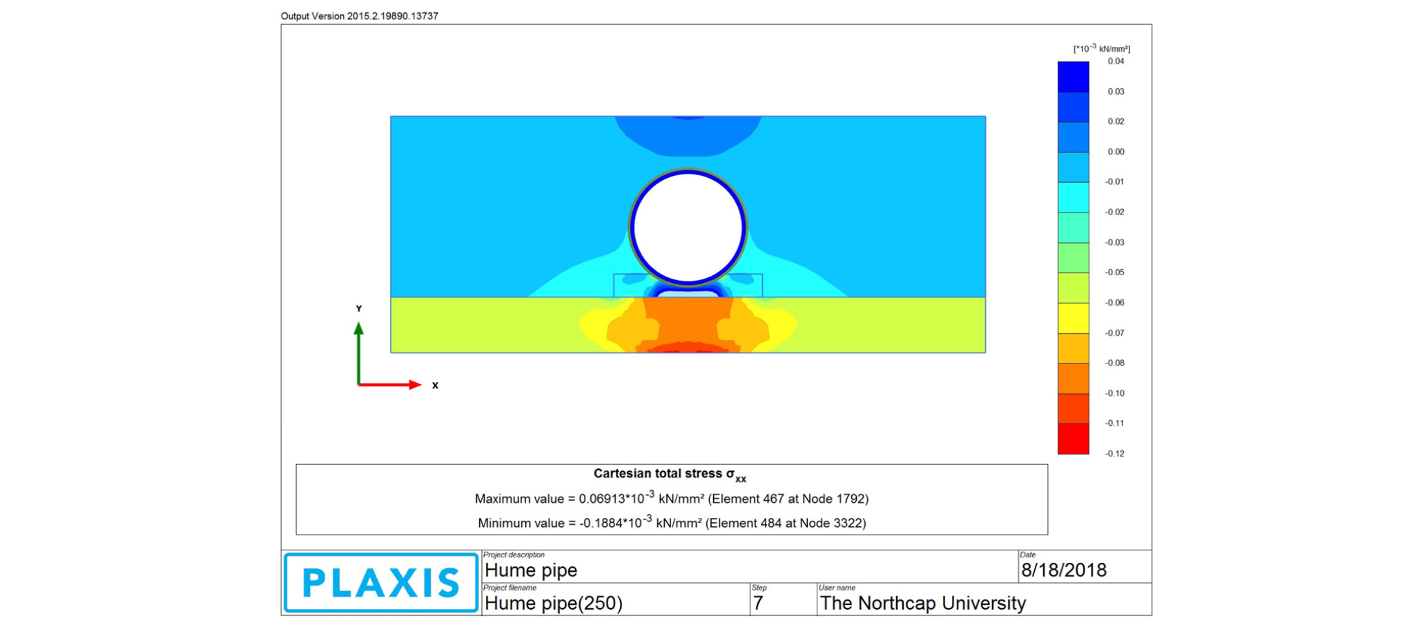
Presently 100 mm PCC was constructed as the base platform for the Hume pipe and headwall. If the thickness is increased it can effectively support the structure and thus can resist the failure. Figure 7.2 and 7.3 shows the stress development for a 200 mm and 250 mm thick PCC respectively. It can be observed from here the maximum value of stress has been reduced to 80 kN/m2 and 69 kN/m2 respectively for 200 mm and 250 mm thick PCC base.
Increasing the compaction of the subgrade soil
As the subgrade soil was found to have compaction of 85% only, it is acting as a fill material and does not able to share the load. However, if the soil is well compacted and higher density can be achieved; it can be helpful in distributing the load properly.
Conclusion
Following conclusions can be drawn from the study:
∙ Forensic analysis of failed structures/ buildings based on deformation data can directly or indirectly contributes in the assessment of the most probable future damages to the structure, which can occur in future.
∙ Problems related with quality of material and methods of construction in forensic analysis are important and can prevent faulty construction at any stage of the construction as revealed with the outcome of the present study, which shows improper compaction leads to failure of the head wall.
∙ One of the most credible hypothesis regarding this case study i.e. failure of the head wall was crack development in headwall owing to lack of proper compaction of soil below foundation of culverts and no time gap between the casting of headwall and its foundation.
